In 2012 I helped put on an event for newbies who were interested in electronics or audio build their first amplifier. We called it Amp Camp. My largest contribution to the camp was to design and machine 50 (!) chassis for our 25 attendees. We were lucky enough to work with a very well regarded designer, Nelson Pass, who supplied the circuit design and many of the parts for that camp. Despite selling commercial amplifiers, Pass has been active in the DIY community for many years and extremely generous in sharing his designs, experience, advice, and even his personal stockpile of parts. He wrote an article describing the design and his process and reasoning for the design decisions he made.
Amp Camp Amp #1
Most of the constraints he placed on the design have to do with accessibility for new builders. Among them:
Switching PSU to prevent exposure to mains voltage
Low parts count for simplicity
Low parts cost
A thread on diyAudio quickly sprang up and is still very active today.
In true diy fashion, there have been many variations and changes to the circuit over the years. Since the inaugural camp, diyAudio has offered a kit in their store, where it has seen high demand. The current version of the diyAudio kit comes in a beautiful aluminum case with options to turn one stereo unit into a mono unit by connecting the channels in bridge or parallel mode for more power. It is clearly a hit in the diy scene.
Objectives:
A return to form for the Amp Camp Amp. Above all, ease of assembly and low cost. Accessibility is the name of the game for this Amp Camp Amp variation. My intent is not to make the best performing ACA, but the best design for someone who is interested in our hobby with little to no build experience.
Results to date:
An even easier to build ACA (1.6) for about $80 per channel in low quantities, if using non-premium parts. The cost comes down when building more as a batch. I built 2 channels and had an unexperienced friend build 2 channels for a first prototype run about 2 years ago and have been using them in my desk stereo system since. I have sat on this design for a while now and figured it was time to finally write it up for sharing. The amp you see below is a single channel.
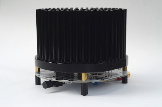
The enclosure presents the biggest opportunity to cut cost in this amplifier (and most other DIY amps). There a few critical functions that an enclosure performs.
1. Heatsink
2. Finger-proofing
3. Aesthetic
I selected a heatsink meant for LED lights. Typical "grow light" heatsinks are now produced in large quantities and are one of the more economical large passive heatsinks available. The one I've selected is a circular forged pin heatsink 120mm diameter and 70mm tall (4.7" × 2.75"). I estimate its thermal resistance at around 0.9°C/Watt. It cost $19 with free shipping.
Another advantage of the LED heatsink is that the base plate is meant to be horizontal with the pins sticking up (and LEDs pointing down). This is what makes the "caseless" design a bit more practical. By placing the PCB below the heatsink it provides a bit of protection for the components underneath and IMHO, some visual interest. Standoffs hold the whole thing up off the table and no other enclosure parts are needed since the amp operates at a touch safe voltage.
Board layout and parts selection:
In the interest of beginner friendliness, I've elected to print component values on the board and line up all the small resistors according to their numbered designation. The large capacitors lay down flat to minimize the overall height (currently 96mm / 3.8" tall). The heatsink is "grounded" through brass standoffs to the PCB mounting holes. Nylon standoffs screw into the brass standoffs so they may act as somewhat less scratchy feet for the amp to sit on. I added a bit of camp themed artwork to the back side of the PCB along with the simplified circuit from Pass' original article. I chose white soldermask because I think it makes the art look good, but it's quite difficult to see the traces ¯\_(ツ)_/¯


In an attempt to make assembly as easy as possible, all the connectors and the power switch are mounted to the PCB. Look ma, no wires! PCB mount power jacks and and RCA inputs are commonly available. Binding posts are less common. This design uses a right angle screw terminal with a 5 way binding post screwed into it. The threads are secured with a bit of solder. Because the binding posts and screw terminals have a high thermal mass, this is the most difficult part to solder. But even a beginner with patience and a higher powered soldering iron should be able to make it work.

These LED heatsinks often come with pre-tapped holes with spacing for the most common LED modules and lenses. I aligned the MOSFETs with the furthest apart M3 holes and used the M4 holes near the edges for the standoffs.


Future improvements and changes:
- Add more info to silkscreen, e.g. bias voltage. Possibly sacrifice rear side art for complete build instructions.
- Add more output capacitance (this version has 2000uF).
- Replace LSK170 label with something a bit more generic.
- Consider repositioning the LED to shine up through the heatsink pins.
- Consider squaring up the back edge of the board so power and RCA connectors aren't angled.
- Move to a larger 140 x 70mm heatsink for more cooling capability and board area. This design doesn't need it, but I want to continue exploring this physical design while standardizing the heatsink size.
I'd love to incorporate feedback and improvements from the hive mind on diyAudio and gauge interest in boards / kits, no promises though!
Further developments:
A slow moving, inaudible fan above the heatsink will more than double the cooling performance, opening the door for higher power designs in the same form factor. I've started tinkering with some old F5 boards I had laying around and I've started thinking about a 2 channel, single board ACA for bridge / parallel operation. These future projects are the primary reason for moving to a larger PCB / heatsink.
Further developments:
A slow moving, inaudible fan above the heatsink will more than double the cooling performance, opening the door for higher power designs in the same form factor. I've started tinkering with some old F5 boards I had laying around and I've started thinking about a 2 channel, single board ACA for bridge / parallel operation. These future projects are the primary reason for moving to a larger PCB / heatsink.


